The Greatest Guide To Wedge Barriers


18 may be done more promptly, conveniently, and expense successfully. FIG. In particular embodiments, the support 30 may be a steel framework consisting of plates, beam of lights(e. g., I-beams ), and/or other frameworks that are safeguarded within the foundation 14, which might be concrete. At the surface area 12, an upper side 28 of the anchor 30 might be at least partly subjected
, thereby allowing the add-on of the barrier 10 to the support 30. g., threaded holes)in one or more light beams or plates of the support 30 might be revealed to the surface 12. In this way, screws 32 or other mechanical bolts might be utilized to safeguard the obstacle 10 to the anchor 30. As the obstacle 10 is mounted to the surface 12 of the structure 14, collection of debris and other material under the obstacle might be reduced, and parts of the bather 10 may not be subjected to below grade environments. As shown by referral numeral 52, the training device 50 includes components disposed under the wedge plate 16. As an example, the parts 52 underneath the wedge plate 16 may consist of an electromechanical actuator, a cam, one or even more camera surfaces, and so forth. Additionally, the training mechanism 50 includes a springtime setting up 54
The springtime rod 58 is paired to a camera(e. g., camera 80 displayed in FIG. 4) of the lifting mechanism 50. The springs 60 disposed regarding the spring rod 58 are kept in compression by springtime supports 62, consisting of a dealt with spring assistance 64. That is, the fixed springtime support 64 is repaired relative to the foundation 14 and the remainder of the bather 10.
The smart Trick of Wedge Barriers That Nobody is Talking About
The continuing to be force used to
the cam camera deploy release wedge plate 16 may might provided given an electromechanical actuator 84 or other various other. The springtime assembly 54 and the actuator 84(e. Wedge Barriers. g., electromechanical actuator)may run with each other to convert the cam and lift the wedge plate 16.
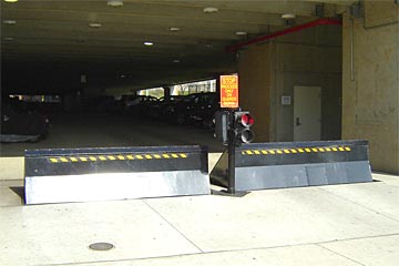
As mentioned above, the spring assembly 54 puts in a constant pressure on the camera, while the electromechanical actuator might be controlled to put in a variable force on the camera, consequently enabling the lifting and decreasing( i. e., releasing and withdrawing )of the wedge plate 16. In specific embodiments, the continuous pressure applied by the spring assembly 54 might be flexible. g., electromechanical actuator) is impaired. As will be valued, the spring assembly 54 might be covered and safeguarded from debris or various other aspects by a cover plate(e. g., cover plate 68 received FIG. 4) that may be significantly flush with the elevated surface 38 of the foundation 14. As pointed out above, in the deployed placement, the wedge plate 16 serves to obstruct access or travel beyond the barrier 10. The barrier 10(e. g., the wedge plate 16 )may block pedestrians or lorries from accessing a residential or commercial property or pathway. As gone over over, the barrier 10 is affixed to the anchor 30 protected within the foundation 14,
front braces 71. Therefore, the affiliation assemblies 72 may pivot and turn to allow the collapse and extension of the linkage assemblies 72 during retraction and implementation of the bather 10. The affiliation assemblies 72 cause motion of the wedge plate 16 to be limited. If a lorry is taking a trip in the direction of the released wedge plate 16(e. For example, in one situation, the security legs 86 may be prolonged throughoutmaintenance of the barrier 10. When the safety legs 86 are this article deployed, the security legs 86 sustain the weight of the wedge plate 16 versus the surface area 12. Consequently, the training mechanism 50 may be shut off, serviced, eliminated, changed, and our website so forth. FIG. 5 is partial viewpoint sight of a personification of the surface-mounted wedge-style obstacle 10, highlighting the web cam 80 and the webcam surfaces 82 of the lifting mechanism 50. Specifically, two cam surfaces 82, which are referred to as lower webcam surface areas 83, are placed below the web cam 80. The lower cam surfaces 83 might be dealt with to the surface area 12 (e. As an example, the lower cam surfaces 83 and the placing plate 85 might form a solitary item that is protected to the anchor 30 by screws or various other mechanical fasteners. Furthermore, two cam surface areas 82, which are described as top webcam surfaces 87, are placed above the cam 80 and coupled to (e. In other personifications, stepping in layers or plates may be placed in between the surface 12 and the lower cam surface areas 83 and/or the wedge plate 16 and the upper cam surface areas 87 As stated over, the camera
80 equates along the cam surface areas 82 when the wedge plate 16 is raised from the withdrawed setting to the deployed setting. Additionally, as stated above, the springtime setting up 54 (see FIG. 3 )might offer a pressure acting on the camera 80 in the instructions 102 through spring pole 58, which may minimize the pressure the electromechanical actuator 84 is called for to relate to the cam 80 in order to actuate and raise the wedge plate Check Out Your URL 16. 1 )to the released setting(see FIG. 4). As revealed, the camera 80 consists of track wheels 104(e. g., rollers), which get in touch with and equate along the camera surfaces 82 during procedure.